Seeing some of 3D-printed parts that people used in their cockpit projects, as well as some other printed models, it seemed that 3D printing quality was not good enough for parts requiring visual accuracy without additional refinement.
At last, as 3D printers became more accessible, we have decided to buy one of the cheap Prusa-clone 3D printers. Having reviewed several similar models, we chose FLSun i3 kit with aluminium frame available online at the price of $200.

As I mentioned, the printing quality was a concern, based on the 3D-printed parts we've seen before. The quality of 3D printed objects depends on a lot of factors - temperature and speed, material, printing settings and printer firmware itself.
But it is also clear that printing stability depends on the mechanical parts and assembly quality, so don't expect good results if the kit assembly is sloppy. Having solid mechanics, rigid frame, smooth, precise bearings and straight even shafts goes a long way to provide good printing results.
So, as we received our 3D printer kit, instead of simply assembling it with all the shipped parts to see how it works, we made a point of taking note of any inaccuracies during assembly and took the time to eliminate them.
Here's a list of potential problems we've noticed with our FLSun i3 and the changes we've made, which may come in handy for anyone assembling a 3D-printer from a kit as a basic guide on what to look out for.
While not critical, all of this can potentially affect the finer quality of the print.
1. The square nuts too loose for the frame

This is a minor issue, but may cause inconvenience while assembling the frame.
A lot of M4 square nuts are used to fix things onto the frame, and their square shape is meant to prevent them from turning inside the frame’s slots when fixing the bolts in place.
However, the nuts that came with the package seem to be just barely large enough for that. This may be attributed to the large amount of bevel on their edges, and some of these nuts just started to turn over inside the frame when trying to fix a bolt into position.
If you want to avoid having to manually fix the nuts in place while tightening the bolts, you could either replace them with more fitting nuts (perhaps with less bevelled edges) or add a shim on top of them to keep them in the more narrow part of the slot.
2. Acrylic parts are attached using bolts without shims
Many acrylic parts need to be attached firmly onto the frame. We’ve added shims onto the bolts used there to lower the tension on these parts, to keep them from bending and potentially cracking near the holes.

3. Limiter buttons sensitivity
While the X and Y-axis don’t require much precision with their zero-position, the Z-axis does, as it determines the nozzle's initial position above the printing surface. So, it might be good to replace the Z-axis stopper button with a more precise sensor, to ensure consistent positioning. In our case, even though the button that came with the kit was rather tight, it was accurate in practice, so we left it as it is (after trying a smoother button, which turned out to be not as good in terms of precision). But we've made our own fitting for the button, as the one that came with the kit was not very convenient or reliable.

4. Loose bearing slots
One of the X-axis bearing slots in a 3D-printed part was too lose to fix the bearing in place. This may not be a big problem, as it can potentially fix an issue in case the two X-axis shafts are not completely parallel, but we've decided to make sure the bearing is fixed in place and doesn't slide out of the assembly.
We've done it by making a couple of threaded holes in the plastic to fix the bearing in place with bolts. One of them is also used for the turbo fan.


5. Sliding shaft quality and fitting
The two X-axis shafts where the nozzle assembly is sliding didn’t seem very smooth, and we happened to have a couple in stock from old disassembled Epson (simple 2D) printers, so we replaced them.
However, the holes in the 3D-printed side sections didn't provide a firm fit for these shafts, and the shafts could slide back and forth in them. A good idea would be, similar to what was described for the loose bearing slots, to make a threaded hole in the plastic part and use a bolt in it to fix the shafts in place.

Another problem was that both the top and the bottom fittings for the Z-axis shafts were a little loose, so the shafts weren’t fixed tightly inside them. To improve their fit at the bottom, we’ve made a couple of 3mm aluminium plates attached firmly to the base, with 8mm holes in them providing a very tight fit for the sliding shafts. At the top, we simply used thermal glue to remove the gap in the upper fittings, and added a couple of thin metal separators to better align the vertical shafts.

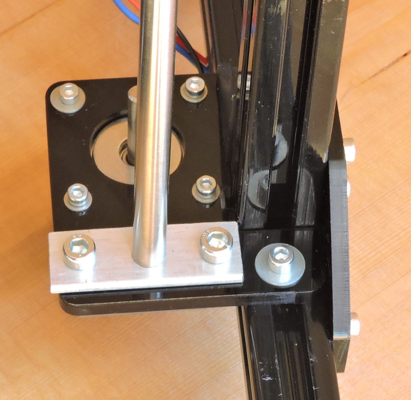

Now, both Z-axis shafts are fitted tight and ensure smooth movement.
6. Stepper motor fixtures
The fixtures for the vertically-aligned stepper motors (1 for Y-axis, 2 for Z-axis) bend a little under their weight. This is relatively minor, but may potentially cause problems with precision, especially for the worm-gear driving Z-axis motors if the bending causes them to shift height a little during movement.
So we just eliminated the gap between the motors and the printer’s frame by inserting metal strips of the appropriate thickness in the gaps.


7. Overall frame rigidity and electronics placement
The way the vertical frame is assembled in this kit may have enough rigidity for certain quality of printing, but it’s still reasonable to improve it, as it’s only attached to the base with a few bolts at the bottom.
We were first thinking of making it a triangular frame by adding a pair of diagonal metal beams. However, we were also thinking of ways to come up with more convenient placement for electronics and the filament spool, and decided that we want to make the printer’s body partially closed.
Placing an acrylic glass plane on the diagonal beams would potentially interfere with printing large enough models, so instead we’ve made a more complex metal frame, with convenient placement of all the electronics.


A minor addition we've also made is a separate box for the printer's LCD, made out of an old modem casing. It looks neat, and we thought it would be convenient instead of fixing it onto the printer's frame.

8. Filament spool casing
It is known that PLA filament is sensitive to ambient air humidity, so we’ve made a casing for it.
Some plastic microwave Tupperware of the appropriate size turned out to fit great for this purpose.


A spindle for conveniently holding the filament spool was later printed on the 3D printer itself.


Conclusion
Right from the first print, it was evident that all the modifications paid off. With 0.2mm printing precision, the quality of the print was nearly perfect, without wobbling on any axis and with smooth, even layers.
 |
| The first print. Draft quality (0.2mm layers) |
Selecting 0.1mm precision, the quality became even more clear. When printing a round vertical rod, no discrepancies in layers are visible at all.
The bottom line here: the quality of the mechanical parts and the assembly go a long way in ensuring printing precision.
When each axis of the printer has smooth movement with no deviations, high quality results can be achieved right on the first print, provided the printer also has good program firmware.
 |
| The width of this part is 10mm. No discrepancies between layers are visible. |
 |
Printed ball joint. The ball's diameter is 14mm. |